Lightning and Surge Protection for Airport Buildings
Lightning and Surge Protection for Airport Buildings and potential risks Due to Direct and indirect Lightning
Airports are complex and sophisticated infrastructures that serve as vital global transportation centers. Outfitted with cutting-edge technology systems, airport buildings operate around the clock to handle thousands of flights and millions of passengers. Given their important roles, these buildings must feature robust lightning and surge protection systems to guard against electrical disturbances, particularly surge voltage incidents.

This blog covers the common requirements and standard practice for the overall design, installation, construction, and evaluation of the following grounding systems in airport facilities:
a. Bonding Requirements
b. Lightning Protection System Requirements
c. Earth Electrode System (EES) Requirements
d. Power Distribution System Grounding Compliance
e. Surge Protective Device (SPD) Requirements
f. Grounding and Bonding Requirements
g. Shielding Requirements
Bonding Requirements
This section covers the following topics:
a. Dissimilar Metals Compatibility Requirements
b. Methods of Bonding
c. Bonding Connection Installation Requirements
d. Hardware for Bonding Jumpers and Straps
Methods of Bonding Direct bonding techniques include:
a. Exothermic Welds. Exothermic welds are permitted for any bond connection specified herein.
b. Hydraulically crimped terminations. You can use crimped terminations as an alternative technique to facilitate the installation of connections in permanently concealed or inaccessible locations.
c. Welded Assemblies. The metal fabrication assembly process is constructed by welding the joints between the individual components.
d. Mechanical Connections. Electrical bond connections are constructed with bolted assemblies.
e. Brazing and Soldering. The bond connections cannot use the metal-joining process formed by brazing or soldering a filler metal.
f. Silver Soldering: To improve conductivity, silver soft soldering material may be applied for the bonding of enclosure shielding joints that have already been secured with mechanical fasteners. Importantly, mechanical fasteners must be attached before the application of solder to prevent cold solder joints. Furthermore, it is essential to note that soft soldering techniques are not permitted as a method for providing mechanical restraint. Therefore, proper adherence to these guidelines is crucial for ensuring effective bonding and conductivity in enclosure shielding applications.
Exothermic Welds
Exothermic welded connections shall be provided for the following applications:
a. Permanent Bonding. Permanent bonding of copper conductors to metal assemblies or building steel.
b. Underground or Buried Locations:
c. Exposed Exterior Locations: Any exposed location where an exothermic weld connection is possible.
d. Permanently Concealed locations: Identify locations where the connection will remain permanently concealed after completing the fabrication or building construction process.
Inaccessible Locations. Locations rendered inaccessible due to a building feature or other physical constraint that restricts routine access necessary to perform maintenance and visual inspection.
Bolted Connections: Bonding bolts shall be used primarily as mechanical fasteners to hold electrical bonding components in place. Tighten bolts sufficiently to achieve adequate contact pressures for effective bonding, but do not over-tighten them to the extent that deformation of bond members occurs. To prevent loosening of the connection, provide disc springs for connections using bolts 1/4-in. diameter and greater.
Termination Lugs Provide 2-hole termination lugs for connections to ground plates. Provide 2-hole termination lug connections to equipment metal members for conductors size 6 AWG and larger. If the equipment’s metal members do not allow modifications for installing 2-hole lug terminations, you may use 1-hole termination lugs.
The lightning protection system aims to provide preferred paths for lightning discharges to enter or exit the earth safely, thereby preventing damage to facilities, equipment, or personnel. Key components of the system include air terminals, roof and down conductors connecting to the Earthing System (EES), the EES itself, and Surge Protection Devices (SPDs). Together, these elements work effectively to dissipate lightning energy. Importantly, the system must meet or exceed FAA standards and orders, specifically adhering to NFPA 780 for installation and UL 96A for installation requirements. Due to the high-risk index of many NAS facilities, authorities mandate enhanced lightning protection measures that exceed the minimum NFPA 780 standards.
NFPA 780 cable sizing requirements. Provide Class II or larger rated materials, as specified in NFPA 780, for the following:
a. Air Terminals
b. Main and Down Conductors
c. Bonding Conductors
Lightning Protection System—Air Terminals Air terminals must be solid copper, bronze, or aluminum, with stainless steel used in areas prone to corrosion. Copper terminals may have nickel plating. Each air terminal should be a minimum of 12 inches high, with a diameter of at least 1/2 inch for copper and 5/8 inch for aluminum, and feature sharp, blunt, or approved protective tips. Installation must comply with NFPA 780 and UL 96A. Closer spacing is allowed for unique geometries, and terminals should extend at least 10 inches above the protected object. To prevent hazards for personnel, particularly near walking surfaces, the terminal height should be at least 5 feet above adjacent surfaces. If mounting directly on the object is not feasible, position air terminals nearby and bond the metallic object to the lightning protection system to ensure effective protection.
Mast Poles Used For Air Terminal Installation Air terminals installed on mast poles shall be at least 2 feet tall and extend a minimum of 10 inches. above the top of the mast pole. Provide a down conductor installed on the exterior of the mast pole. air terminal and down conductor shall be fastened to the pole following NFPA 780. Connect the air terminal to the nearest main roof conductor or down conductor. If a roof or down conductor is not available, bond directly to the EES.

Ground rods Installation of ground rods shall meet the following requirements:
a. Material and Size. Ground rods shall be copper or copper-clad steel, a minimum of 10 ft long and 3/4 in. diameter. Rod cladding shall not be less than 1/100 in. thick.
b. Spacing. Ground rods shall be as widely spaced as possible and, in no case, spaced less than one-rod length. Nominal spacing between ground rods is between two and three times the rod length.
c. Depth of Rods. Install top-of-ground rods at least 1 ft below grade level or 1 ft below frost depth if required to suit climatic conditions.
d. Location. Rods shall be located 2 to 6 feet beyond the foundation or exterior footing of the structure, except at locations where abutting sidewalks, equipment, or other obstructions warrant locating rods farther away from the foundation. On buildings with overhangs or sidewalks close, then the ground rods are permitted to be placed at locations further out.
e. Orientation. Ground rods shall be driven at 90 degrees (vertical) orientation to finish grade. If ground rods cannot be driven vertically to their full length
Surge Protection Device (SPD) Requirements
SPDs shall be provided at locations where electrical power systems are susceptible to conducted power line surges. SPD equipment functional performance requirements are detailed. The selection of appropriate SPD depends on location and application. The SPDs and transient suppression provided at electronic equipment power line entrances shall be coordinated as required.
SPD for Power Distribution System SPDs shall be provided at the following locations:
a. Service Disconnecting Means. Provide SPD on the load side of the SDM.
b. Facility Entrance Point. Provide SPD on the load side of a facility entrance point. For example, if the facility entrance point is within a NAS electronic equipment room, the SPD is required at the first distribution panel board that supplies the branch panel boards within the room.
c. Transfer Switch, Switchboard, or Panelboard. Provide SPD either on the load side of an engine generator transfer switch or the first switchboard or distribution panel board located downstream of the transfer switch.
d. Panel boards Feeding Building Exterior Loads. Provide SPDs at panel boards that supply branch circuit wiring exiting the building to serve exterior equipment.
e. Secondary Transformer. Provide SPD at a separately derived power source that feeds electronic equipment.
SPD for Facility Entrance Equipment
SPDs shall be provided at the SDM, at all facility entrance penetrations, and feeder and branch panel boards. Additional SPDs shall be provided at the power line entrances to operational electronic equipment.
SPD for Power Distribution Feeders and Panelboards
SPDs shall be installed on switchgear, panel boards, and disconnect switches providing service to NAS operational equipment or supplying exterior circuits.
Examples of exterior circuits include obstruction lights, convenience outlets, guard houses, security systems, electric gates, and feeds to other facilities.
Lightning and Surge Protection for Airport
SPDs shall be installed close to the panel boards they serve, following the manufacturer’s instructions. A feeder or branch panel board SPD must include an overcurrent protection device (OCPD), such as a fuse or circuit breaker, integrated into the SPD or installed within the panel board and dedicated to the SPD. The OCPD shall not increase the SPD’s clamp voltage by more than 5% and must handle surge currents up to 40 kA without tripping. For exterior circuits, overcurrent devices must allow all surge currents to pass without disruption. You must size and coordinate both internal and external OCPDs, along with the SPD’s short circuit ratings, according to the NEC, ensuring they are designed to be field resettable or replaceable.
Install SPDs close to the panel board or equipment they protect; furthermore, keep conductors as short as possible.
SPD for Signal, Control, and Data Line Surge Protection Provide SPDs at the following locations: a. Facility entrances,
b. Entrances to NAS electronic equipment
c. Entrances to electronic equipment installed by the telecommunication service provider.


Surge protection
External lightning protection systems do not prevent the effects of distant or cloud-to-cloud lightning, nor do they mitigate the electromagnetic fields generated by lightning currents as they travel from the cloud to the ground. Therefore, it is essential to protect antennas, associated equipment, and critical infrastructure within airport buildings against transient surges to ensure uninterrupted operations.
Surge protection is, without a doubt, crucial for any comprehensive lightning protection system. Specifically, while lightning may initially strike the exterior of a structure, the resulting induced surges can, in fact, cause significant damage to sensitive and expensive equipment inside. Consequently, it is essential to implement effective surge protection measures to mitigate this risk. Moreover, by investing in surge protection devices, you not only safeguard your equipment but also enhance the overall resilience of your electrical systems. Therefore, integrating surge protection into your lightning protection strategy is a vital step in ensuring the safety and longevity of your infrastructure.

1. Type 1 Surge Protectors: Install these devices at the main entrance point of the building, typically where the power supply enters. They are designed to handle large surges directly from lightning strikes and prevent these surges from entering the building’s electrical system.
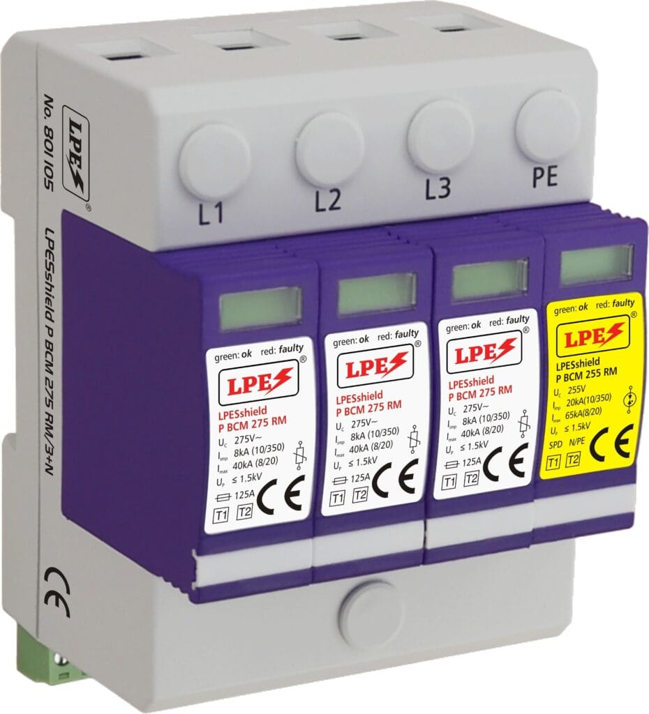
LPESshield series Combined technology for direct lightning protector, TYPE 1 SPD, capable of withstanding a peak current of 30kA per with a 10/350 wave μs and with a residual voltage lower than 1.5kV.
2. Type 2 Surge Protective Devices: Positioned strategically at downstream sub-distribution boards, these devices protect the building’s internal electrical networks. Moreover, they manage the surges that have passed through the Type 1 devices and further safeguard critical circuits and electrical distribution systems. In doing so, they ensure that the building’s electrical infrastructure remains secure and functional.

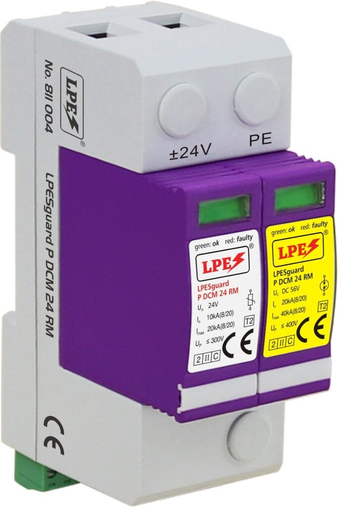
LPESguard Series for DC-DC power supply line protector modules protection is able to withstand a current of 20kA with wave 8/20μs and with a residual voltage of less than 1.5kV.

3. Type 3 Surge Protectors: These are installed close to the terminal devices and sensitive equipment. Specifically, their role is to protect individual devices from any remaining surge that might have escaped the previous stages. As a result, surge protection effectively shields equipment such as antennas, TVs, and communication systems from potential damage.
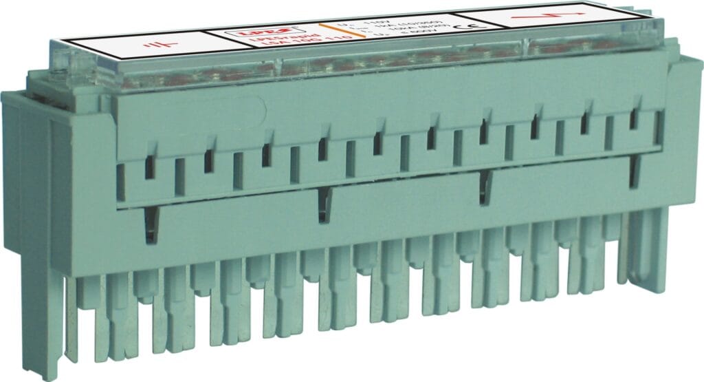
LPESpatch series
SPDs are crucial for protecting antenna systems from lightning and transient voltage surges. LPES offers a wide range of SPDs designed for coaxial lines, ensuring optimal protection without affecting signal quality.
LPES’s coaxial SPDs feature various connectors, handle high surge currents (up to 10kA per pole, 8/20 μs), and have low residual voltage.
Investing in LPES’s coaxial SPDs not only protects your antenna system but also significantly minimizes downtime due to electrical surges. Moreover, by implementing these protective devices, you can enhance the reliability of your communication infrastructure. Consequently, this proactive measure ensures uninterrupted operations and ultimately contributes to improved safety and efficiency. Therefore, choosing LPES’s coaxial SPDs is a strategic decision that safeguards your assets and supports operational continuity in the face of unpredictable electrical events.
Conclusion
Given the complex infrastructure and critical nature of airport operations, lightning and surge protection for airport buildings are indispensable for ensuring safety, minimizing downtime, and protecting valuable equipment. Specifically, from grounding and bonding systems to SPDs at every power distribution point, robust protective measures are crucial for maintaining operational continuity and passenger safety.
Furthermore, LPES offers a wide range of customized lightning and surge protection solutions designed to meet the unique requirements of airport facilities. By adhering to industry standards and leveraging advanced technologies like LPESshield, LPESguard, and LPESpatch, airports can achieve optimal electrical safety and system reliability. Ultimately, investing in these comprehensive solutions not only enhances protection but also fosters confidence in the safety and efficiency of airport operations.
Contact us now for the best solutions!

